Apr 27, 2010

Shadow blur with PCF and Gaussian filter

Long time back, GPU Gems introduced how to soften shadow with Percentage Closer Filter: http://http.developer.nvidia.com/GPUGems/gpugems_ch11.html

The article fetches eight times and get a similar result to sixteen times fetching.

I have tried both ways but I wasn't satisfied with them.

As the article explains the problem on the shadow map is that we needs to get binary depth testing results first. We cannot just blur the shadow depth values.

To get a correct Gaussian blur result, we first need to get sixteen texels from the shadow map. Then we compare those values with the actual depth value. Now we need to use Gaussian blur on those binary testing results.

The article on the GPU Gems just takes the average on them, but the quality can be much more improved with Gaussian blur and/or Bilinear filter.

We can use a 3x3 Gaussian mask on 4x4 texels. Thus we will get four boolean values. Then we can take bilinear filter on them.

To improve the result even further, we can calculate floating values from the depth testing, rather than just boolean values.
float depthOffset = 0.001;

float depth00 = GetDepth( uv + float2( -1.5, -1.5 ) );

float brightness00 = saturate( ( depth00 - ( actualDepth - depthOffset ) ) / ( 2* depthOffset ) );

// do the same thing on different offsets.
This approach is trying to estimate how much the pixel is open to the light; I tried to apply SSAO trick on the shadow map, but in a simpler way.

The result was looking good, but I am still looking for a better way, because sixteen texel fetching seems too expensive.

One way to improve the performance can be to fetch half or quarter of them and fetch others only when those depth testing results differ.

Apr 25, 2010

Why does light leak happen on the soft shadow map?

Today I have arrived at certain conclusion about soft shadow map technique. I am trying to describe it now.

Variance shadow map (or VSM) Convolution shadow map (or CSM) and Exponential shadow map (or ESM) all have light leaking problem. On papers of VSM this problem is referred as "light bleeding". Here I assume "light bleeding" and "light leaking" are the same problem.
The light leaking artifact is actually the source of softness of the shadow. What I am proposing here to solve the light leaking problem is to differentiate inner penumbra region from outer penumbra region; I will explain more latter.

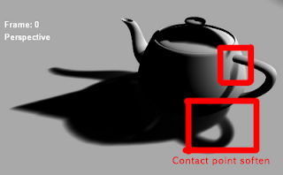
A screen shot of Exponential shadow map is below:The screen shot was referred as "no bleeding", but the fact is it is still bleeding and it has physically wrong softness on the contact points.The shadow around the contact points is supposed to be sharp because they are affected by high frequency light most. The contact point soften problem is actually a little bit different version of the light leaking problem. For example, if we put two pieces of papers very closely, the second paper which is supposed to be under shadow will get soften shadow due to the short distance.

First the reason why we have light leaking problem on shadow map retrieving methods is that we are trying to estimate information of places under the shadow map while the shadow map hold non of information of them.

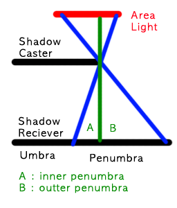
There can be two types of penumbra region with respect to the shadow map. I call them inner penumbra and outer penumbra. Inner penumbra is penumbra region that is not visible from shadow map. Outer penumbra is penumbra region that is visible from shadow map.Whenever we attempt to soften "inner penumbra" region, we are using estimated values. It is because the shadow map doesn't see the inner penumbra part so that there is no information on the shadow map. The way to estimate the information behind the shadow map is causing the light leaking problem.

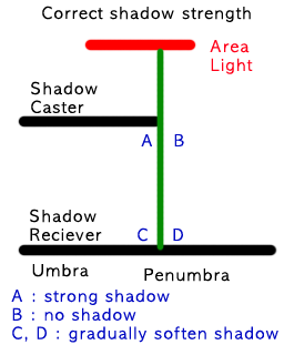
A physically correct shadow strength calculation should be like this:Note that we must differentiate "B and D" from "A and C". It is because B part gets full of light while A part doesn't get any. If we use the same calculation on inner penumbra region( A and C ) and outer penumbra region ( B and D ), the result must be wrong.

The problem is on "A and C" part with VSM and ESP.

The calculation of VSM is like this:
float bOuterPenumbra = ( depthOnShadowMap >= actualDepth );

float brightness = variance / ( variance + pow( actualDepth - depthOnShadowMap, 2 ) );

float finalBrightness = max( bOuterPenumbra, brightness );
This will make "A" part brighter than "C" part, which is opposite to the correct shadow model. This will make stronger shadow on "C" part and softer shadow on "A".

Note that VSM does not count the outer penumbra region into the calculation. In order words VSM is working with inner penumbra region not with outer penumbra region.

ESM does the smiliar calculation way of VSM. It reduced light leaking problem but now it causes contact point soften problem. It is because ESM considers depth values only regardless how much the depth values are interpolated. By this reason, the light leaking problem is moved from "C" part to "A" part so that it appears to be soften contact points.

To address this light leaking problem, we need to give the softness on the outer penumbra rather than the inner penumbra. With respect to the fact that the shadow map holds no information of inner penumbra region, it makes more sense to apply shadow softening on the outer penumbra region.

The calculation will be like this:
const float e = 2.71828183;
const expConst = -5.0;

const bool bUnderShadow = ( actualDepth > depthOnShadowMap );

const float brightness = ( bUnderShadow ? 0.0 : ( 1 - saturate( pow( e, expConst * actualDepth ) / pow( e, expConst * expFromExpMap ) ) ) );
There are some problems on this approach.

One of them is that we cannot use "second depth rendering" trick on shadow map rendering phase. Second depth rendering is to render back face on the shadow map rather than front face. It is very helpful to reduce the shadow swimming problem and "surface acne" problem. Since the softness calculation relies on the front face depth, we can no longer use second depth rendering.

Another problem is that we must hold the original shadow map in order to differentiate inner penumbra and outer penumbra. When we want to pre-filter the shadow map as ESM does, we need to fetch texels on both.

I have some of solutions in my mind and I will post more details after I get enough test results.

Apr 23, 2010

Soft shadow with shadow map...

There were several new innovative shadow map techniques that promised soft shadow. There are Variance shadow map, and Exponential shadow map.

They are using 32bit floating point surfaces and they assumes they work with linear hardware filter. Unfortunately PlayStation3 does not support linear nor bilinear filter for 32bit floating point surface. How am I supposed to get soft shadow?My final choice was a little bit modified version of Percentage Closer Filter, which means I fall back to the bottom line. I modified it to mimic the bilinear filter.

I am not quite happy because I cannot get any benefits from new hardware accelerations. But it seems to work fairly good.

*PS: The screenshot it from here.

Apr 20, 2010

Depth buffer blur with Gaussian filter on PS3

These days I often look at the real shadows of trees or any objects. Strangely they don't look natural or real for me. It makes me thinking of what kind of soft shadow I want to see.

The softness of shadows is from frequency of light. Around edges the shadow looks sharp, because it is resulted from high frequency. Some of soft shadows are from low light frequency.When we render a shadow map, it is analogous to the HIGH frequency light. It is proper to the shadows close to the object but improper to the shadow far from the object.

We need LOW frequency shadow map for distance shadows. Low frequency shadow map can be retrieved by Gaussian blur. The blurred shadow map must have the same resolution to the original shadow map.

One problem here is again how to blur the shadow buffer which contains encoded values.

Simplest way is to sample nine times and calculate Gaussian blur, but this way will be too slow.

I have already described how to get blurred depth buffer with linear filter before: http://wrice.blogspot.com/2010/04/blurring-depth-buffer-with-linear.html

Today I found that I can also do this with the Gaussian filter on PS3. The trick is very similar to the one with linear filter, but it needs more buffer bits on each channel. And this is not for down sampling but only for blur.

The Gaussian filter on PS3 does "[ 1, 2, 1 ] [ 2, 4, 2 ] [ 1, 2, 1 ] / 16".
Since it divides by 16 ( =2^4 ), we need to have 4 bits as buffer on each color channel.

It means that we can use 4bits on Red channel, 4 bits on Blue channel, 4 bits on Green channel, and 8 bits on Alpha channel. Therefore, we can use total 20bits, which is large enough.

The way to use those shadow maps is to sample on the non-blurred shadow map first and sample one more time on the most blurred shadow map. The difference value between those two sampled values will represent how much the shadow needs to be blurred.

Apr 19, 2010

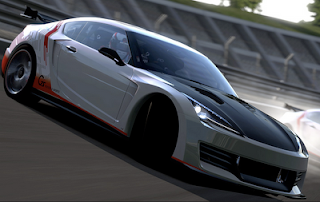
From gran turismo 5 movie clips

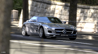
Today I was looking closer to Gran Turismo 5 movie clip.

I found that they are using two types of shadows of cars. One is from directional light and another is ambient occlusion.

The shadow from the directional light is done by shadow map. Each car seems to hold their own shadow map.
As you can see from the screen shot above, those two types of shadows don't seem to get along well.

An impressive part is reflections on the car's body. The reflection looks very clear and covers body and glasses part very nicely. I guess they are stream in and out pre-baked environment map rather than rendering them at run-time.

I will be very surprised if the environment map is rendered at run-time. One way to figure out is to see whether other cars are reflected on the car's body or not. I couldn't find that kind of situations from the movie clip but I can test it latter.I tried to see aliasing issues but the movie clip did not carry enough details on edges. HDR was covering edge parts smoothly and Depth of Filed made the look smoother. Slightly shaking camera up and down made the scene more realistic.

God Of War 3 has seamless pre rendered cut scenes

Today I am very sure that the cut scenes in god of war 3 are pre-rendered not real-time rendering.

The way I figured out is that the shadow looks very very nicer and softer on the pre-rendered cut scenes while the shadow isn't that much smooth during the game play.
I should say it was almost indistinguishable if I didn't pay enough attention on the shadow.

It is often hard tasks to match the pre-rendered cut scenes and the actual game scenes, because 3DS Max or Maya generates quite different look and feel of the background or characters from what the actual game engine generates. I am guessing that they might have pre-rendering tools with the game engine, not directly from Max/Maya.

It could probably save some face motion animation data by using pre-rendered cut scenes.

Apr 18, 2010

Real-time Ray-tracing with PS3s.

I found some of YouTube movie clips of Real-time ray-tracing with several PS3s.

http://www.youtube.com/watch?v=oLte5f34ya8&feature=related
http://www.youtube.com/watch?v=nUouN-NJVF4

It is very interesting. They are using SPUs only due to the limitation of supervisor mode. Each PS3 has six SPUs available.
However, it still does not look fast enough for game rendering.
The first demonstration uses three PS3s and the scene is static.
The next one is using seven PS3s and the scene is dynamic.

I think if real-time ray-tracing is feasible with two or three PS3, then we may be able to see any commercial or non-commercial games potentially.. :D

God of war 3 uses light cube

Today I found two interesting visual bugs on God Of War 3.
The screen shot above shows it uses light cube. Note the light boundary bends on leg part. It means that the light boundary is aligned to the world space not to the screen space. In other words it is not screen quad but light cube in the world space.

It also means that they are using deferred shading or light pre-pass. I don't know which one it is. I don't see much variety of materials, so it can be deferred but I don't think there can be any reasons to use deferred shading over light pre-pass these days. If I can see any sophisticated shaders such as parallax mapping, I will be able to conclude it is using light pre-pass, but I haven't seen any of them yet.

It is common to use light cube than light sphere which I am using on our project currently. I think saving the cost on fragment shader will be more efficient than saving that of vertex shader. I may be wrong, because I haven't seen any games using light sphere yet.

Another visual bug is about shadow.The first screen shot shows a badly aliased shadow on the wall. The second screen shot shows anti-aliased shadow on the character. In other words, the shadow on the wall looks jig-jagged while the same shadow looks very smooth on the character.

I am guess it is because they use different resolutions on different objects for shadow map. It makes sense to handle the shadows differently on characters from on static objects.

One more interesting thing is the aliased shadow on the wall looks still not too bad and somehow blurred. I don't know how they did it.

Apr 13, 2010

Projection matrix and inversed depth value.

On DirectX coordination system, which is left hand coordinate, the center of the screen is ( x, y, z ) = ( 0, 0, [0~1] ); "[0-1]" means from zero to one. Top right corner of the screen is ( x, y , z ) = ( 1, 1, 0 ) and bottom left of the screen is ( x, y, z ) = ( -1, -1, 0 ).

When we show the 3D points or lines on the screen, we use perspective way rather than orthographical way. In other word, a far object appears to be smaller while a closer object appears to be bigger.

The way we do this is to divide x and y values by z value. When z value is bigger, x/z and y/z get smaller. In other words the points or lines get closer to the center of the screen when the z value is bigger, because the center is ( 0, 0, [0-1] ).

The matrix will be like this:
[ 1, 0, 0, 0 ] [ x ]
[ 0, 1, 0, 0 ] [ y ]
[ 0, 0, 1, 0 ] [ z ]
[ 0, 0, 1, 0 ] [ 1 ]
=
[ x ]
[ y ]
[ z ]
[ z ]

We always divide x, y, and z values by the last value, w, in order to make the w value to be 1.
[ x / z ]
[ y / z ]
[ z / z ]
[ 1 ]

Now we see there is a problem on Z value. Z will be always 1. In computer graphics, Z value 1 means deepest inside of the screen. In order words, the most far objects have z value one, while the closest objects have z value zero in DirectX.

In order to solve this problem we use this matrix instead:
[ 1, 0, 0, 0 ]
[ 0, 1, 0, 0 ]
[ 0, 0, 1, -1 ]
[ 0, 0, 1, 0 ]

The result is:
[ x / z ]
[ y / z ]
[ ( z - 1 ) / z ]
[ 1 ]

Note the z value is now ( z - 1 ) / z. It is equals to ( 1 - 1 / z ).Now far objects will have less than one but closer to one. Since the Z value is inversed the values are not evenly distributed. For far objects, the projected Z values would not vary much. For example, projected Z for Z value, 100, is 1 - 1/100 = 0.99 and projected Z of Z value, 200, is 0.995. The Z values are double times different but the projected Z value differs only 0.005. In other words, for far objects the projected Z value is less sensitive while for closer objects the projected Z value is more sensitive.

This is a preferable result on perspective view, because we can notice depth difference of closer objects more than far objects.

One problem I realized is that by this projection matrix the negative Z value may result in a very big positive value. For example, for Z value, -2, which means the object is behind of the camera, the projected Z value is 1 + 1 / 2 = 1.5, meaning that it is at infinitely far front side not on back side. To solve this problem, we need to make sure the Z value always ranges from zero or positive value.

Lawyers

Lawyers may do good if you hired them.
They are definitely mean if someone else hired them.
Thus they are either definitely mean or may do good.
In other words they are averagely closer to mean:
( "may do good" + "definitely mean" ) / 2 = "mean"
We may need them sometimes but I don't think their job is productive. It is like soldiers, which are powerful but don't produce any.I wish not to face them.

Tessellation on XBox360

Today I found that XBox360 has tessellation feature.

I thought tessellation or geometry shader is supported from DirectX10 so that I was very excited by finding this. Tessellation is simply saying when I pass one triangle, I can use more than one triangles as the result. It is supposed to be fast and efficient due to hardware support.Actually I haven't been paying attention on geometry shader or tessellation, because I thought we cannot use it yet. I always skipped those parts when I read books. Now I need to track back and check what kind of techniques I can use with it.

It seems like PS3 doesn't have any similar functionality. Sony might think of SPU as the counter part.

Unfortunately the XBox360 SDK document doesn't explain about the tessellation at detail; for example performance or caveats. In addition, I haven't heard any XBox360 games have been using the tessellation feature before. It makes me wonder how useful it will be.

Observation of shadow map in God Of War3

Today I have played a little bit of God Of War 3.

I know there was a presentation on GDC 2010 about shadow in God Of War3, but I cannot get it. Therefore I had to guess by looking at the result.

From by observation, it is definitely doing multi-sampling on a shadow map. Probably it does percentage closer sampling, because the penumbra reason is almost one pixel distance on shadow map. It is more clearly noticeable when the shadow is drawn on a edge.
I saw the shadow is often jumping. It gives me the impression that the shadow map is dynamically moving. It may moved to find the best angle between shadow map and the shadow receiver. It is also possible the position of shadow map is predefined by artists. This way reminded me of the shadow implementation of Halo series.

The character has only one shadow even when there are many lights around him.
Black shadow like texture appears when the character is under a shadow, which is similar result with assassin creed 2.

The game also uses static shadows from static objects with the dynamic shadows from characters. They get along well. When a character is inside of the static shadow, the dynamic shadow merges and disappear naturally.

I want to know how actually it works....

Apr 5, 2010

Penumbra shadow map screen shot

I have implemented some part of the penumbra soft shadow map idea. I need more time to implement the actual shadow part, but today I got the penumbra map.

I found that we can use shader programs even with wire frame fill mode; I am not sure whether or not it can be faster than solid fill mode. Therefore I could implement shaders that generate a derivative image directly with rendering wire-frame model.

I like to show some of screen shots.
The first image is the scene from light perspective:
Then, the depth map is generated. The depth values are stored at Red and Green channels.
Finally, the derivative image is generated by rendering wire-frame fill mode:
Note that the leg parts of the elephant looks like blurred. It hasn't been blurred but because their derivative values are small. Thus I can expect that contact points between the disk and the elephant will have sharp shadow.

It fetches five times at quarter resolution and I didn't see any false-positive edges. Since the derivative values are 8bit data, they can be retrieved by linear filter.

Apr 4, 2010

Soft shadow map with wire-frame lines.

After lots of thoughts, I came up with another idea about soft-shadow map.

The basic idea is that we render objects on Wire-frame mode on the shadow map as fourth channel. This wire-frame information is used as edges. Then when we retrieve the depth information from the depth map, we multi-sample on pixels where the wire-frame is rendered; otherwise, we sample only one time.
The idea is based on multi-sampling shadow mapping; for example, Percentage-closer filtering (PCF). It will be very costly if we just multi-sample on every pixels. We want to multi-sample only on edges. However edge detection on shadow map by doing image processing is very hard. My idea is to use 3D model information to get those edges by rendering wire-frame lines.

If we can control the width of wire-frame lines, we can increase the size of penumbra region, which will require more multi-sampling. It will be better if we can have different width on different depth, but it would not be possible sadly. If the fixed width give us bad result, we may need to blur the lines; possibly at lower resolution.

It is also possible to use stencil buffer instead of rendering actual lines on a color buffer. If we are already using a depth buffer on console machines for shadow map, we can reuse the stencil channel at free.
I haven't seen any rendering tricks that use wire-frame information yet. It makes me wonder whether this idea is feasible or not. And although I assume that wire-frame rendering will be cheaper than normal rendering, it may not be true; I need to test this.

I kept looking for any ways to eliminate the multi-sampling cost at all by doing some of pre-processing on the wire-frame image; for example, blurring or pre-calculating. However, I found that it may not be worthy, because each pixel on the shadow map does not correspond to each pixel on the screen. In other words, some of pixels on the shadow map will be used several times while others may not be used at all. In addition, image processing on the shadow depth map is relatively expensive, because each pixel needs to fetch at least two or normally five texels.

Edge detection with wire-frame rendering will give us false-positive a lot. It will be nicer if we can eliminate those wrong edge lines. One way to do this is to use normal information, but I'm not sure whether I can use shader programs on wire-frame mode.

It is also possible to use a derivative image of the shadow map. The derivative image can eliminate those false-positive edges. Taking derivative image will require at least three times of texture fetching per pixel, which is expensive. But if the number of multi-sampling on edge side will be more than three times, taking derivative can be an option as pre-processing. After updating stencil buffer by rendering the wire-frame, we can reduce the cost of 2D image processing with stencil early cull.

Another thing I want to mention is that there are lots of missing information on the shadow map that is necessary for softening penumbra region. Even after the costly pre-calculation on the shadow map, those reconstructed inner-penumbra information is not correct; by inner-penumbra I mean penumbra region inside shadow, while outer-penumbra will be penumbra region out side of shadow. Thus I think it is better to multi-sample latter with the actual depth.

I will try to implement this idea to see feasibility.

Apr 1, 2010

Blurring depth buffer with linear filter.

It happens sometimes that we need to blur the depth buffer, but we cannot use linear filter for depth value.

The reason is that the depth value is encoded into three channels. We use 24 bits for the depth values, and each color channel consists of only 8 bits, so that we have to split the depth value onto three separate color channels. By the reason, if we linearly interpolate each channel of the encoded values, the value will be broken.

My idea to use linear filter for the depth buffer requires two preconditions.
  1. We store the depth values on color buffer not on the depth buffer so that we can control the encoding way.
  2. We want to get the average values from four texels. In order words, this way does not work if we want to linearly interpolate at arbitrary ratio. It has to be exactly at the middle of four texels.
Let's see the reason why depth values cannot be linearly interpolated.
For example we have two values: 257 and 254. Of course the actual depth value ranges from zero to one, but floating point expression is hard to read as an example.

The encoding formula is like this:
  • Blue channel = value % 256
  • Green channel = ( value / 256 ) % 256
  • Red channel = ( value / ( 256 * 256 ) ) % 256
*PS: "%" is modulation operator, which gives us reminder after division.

For the value, 257, the encoded value is [ R, G, B ] = [ 0, 1, 1 ]. For the value, 254, the encoded value is [ R, G, B ] = [ 0, 0, 254 ].

When we sample at exactly middle of the texels, the hardware linear filter will give us the interpolated value, [ R, G, B ] = [ 0, 0, 127 ], because first it calculate values for each channels, and it will truncate the values lower than zero.

The decoded value will be 127; The way to decode is the opposite process of the encoding way: 0 * (256*256) + 0 * 256 + 127. The result we expect is "255", but we got 127.

The problem is at under-flow part. The averaged value on the Green channels is supposed to be 0.5. If we can get the value below than zero, we can correctly reverse back the original value.
0.5 * 256 + 127 = 255.

Thus we need some buffer bits for the truncation. The encoding formula must be changed to:
  • Blue channel = value % 256
  • Green channel = ( ( value / 256 ) % 128 ) * 2
  • Red channel = ( ( value / ( 256 * 128 ) ) % 128 ) * 2
By this encoding way, we will store a value, [ R, G, B ] = [ 0, 2, 1 ], for the value 257 and another value, [ R, G, B ] = [ 0, 0, 254 ], for the value, 254. The linearly interpolated value for each channel is [ R, G, B ] = [ 0, 1, 127 ], and now we can reverse back to the correct average value, 255: ( 0 / 2 ) * ( 256 * 128 ) + ( 1 / 2 ) * 256 + 127.

Since we need to use bilinear filter for 2D image, we need to reserve 2 bits for each channel. Fortunately overflow never happens due to the characteristics of average. Now we can use 6 bits for the Red channel, 6 bits for Green channel, and 8 bits for Blue channel; total 20bits. I assume that each channel has only 8 bits available.

In case that 20 bits are not enough, we can also use the fourth channel, alpha. Then we can use 6 bits for Red, 6 bits for Green, 6 bits for Blue and 8 bits for Alpha; total 26bits, which is big enough for the most cases.

This way should work for depth value blur with the trick I explained before: http://wrice.blogspot.com/2010/03/gaussian-filter-for-anti-alias.html

Please note that this trick does not work when we expect arbitrary linear interpolation; the texel coordinate is not exactly at the middle. It will cause under-flow problem with much higher precision.